


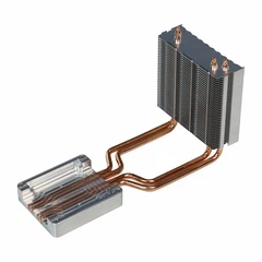
Optimizing the design of an aluminum finned heat sink is crucial for achieving better performance in various applications, especially in electronics where efficient heat dissipation is essential to maintain the reliability and longevity of components. As a supplier of Aluminum Finned Heat Sinks, I have witnessed firsthand the impact of well - designed heat sinks on system performance. In this blog, I will share some key strategies and considerations for optimizing the design of these heat sinks.
Material Selection
The choice of aluminum alloy is the first step in optimizing a heat sink's design. Different aluminum alloys have varying thermal conductivities, mechanical properties, and corrosion resistances. For example, 6063 aluminum alloy is commonly used in heat sink manufacturing due to its good extrudability, moderate strength, and relatively high thermal conductivity of around 201 W/(m·K). On the other hand, 1050 aluminum has a slightly higher thermal conductivity of about 229 W/(m·K), but it has lower mechanical strength. When selecting the material, we need to balance between thermal performance and mechanical requirements. If the heat sink will be subjected to significant mechanical stress, a stronger alloy like 6063 might be a better choice, even though it has a slightly lower thermal conductivity.
Fin Design
The fins of a heat sink play a vital role in enhancing heat transfer. There are several aspects to consider when designing fins.
Fin Shape
Common fin shapes include rectangular, triangular, and pin - shaped fins. Rectangular fins are the most widely used because they are easy to manufacture and provide a large surface area for heat transfer. Triangular fins, however, can offer better heat transfer coefficients in some cases, especially when the fluid flow is laminar. Pin - shaped fins are often used in applications where the fluid flow is complex or when a high degree of heat transfer in multiple directions is required. For example, in a DCC Power Control High - Power Heatsink, the fin shape is carefully selected to maximize heat dissipation based on the specific power requirements and the flow characteristics of the cooling medium.
Fin Thickness and Spacing
The thickness of the fins affects both the mechanical strength and the heat transfer performance. Thicker fins are more robust but may have a lower surface - to - volume ratio, reducing the overall heat transfer efficiency. Thinner fins, on the other hand, can increase the surface area for heat transfer but may be more prone to mechanical damage. The spacing between the fins is also critical. If the fins are too close together, the flow of the cooling fluid (air or liquid) can be restricted, leading to a decrease in heat transfer. Conversely, if the fins are too far apart, the surface area available for heat transfer is reduced. A proper balance must be struck between fin thickness and spacing to optimize performance.
Fin Height
Increasing the fin height can increase the surface area for heat transfer. However, there is a limit to this effect. As the fin height increases, the temperature difference between the base of the fin and the tip decreases, reducing the efficiency of heat transfer along the fin. Additionally, taller fins may increase the pressure drop of the cooling fluid, which can require more power to maintain the flow. Therefore, the fin height should be optimized based on the specific application requirements and the characteristics of the cooling system.
Base Design
The base of the heat sink is in direct contact with the heat source, and its design is crucial for efficient heat transfer.
Base Thickness
A thicker base can provide better heat spreading, which is especially important when the heat source has a non - uniform heat distribution. However, a very thick base can also add unnecessary weight and cost. The optimal base thickness depends on the power density of the heat source and the thermal conductivity of the aluminum alloy used.
Base Surface Finish
A smooth base surface finish can improve the contact between the heat sink and the heat source, reducing the thermal contact resistance. This can be achieved through processes such as machining, grinding, or polishing. In some cases, a thermal interface material (TIM) may also be used between the heat sink base and the heat source to further reduce the contact resistance.
Manufacturing Processes
The manufacturing process used to produce the heat sink can also impact its performance.
Extrusion
Extrusion is a common manufacturing process for aluminum finned heat sinks. It allows for the production of complex fin shapes with high precision and relatively low cost. However, the aspect ratio of the fins (the ratio of fin height to fin thickness) is limited in extrusion. For heat sinks with high - aspect - ratio fins, other manufacturing processes may be required.
Machining
Machining can be used to produce heat sinks with more complex geometries and higher - aspect - ratio fins. It offers greater design flexibility but is generally more expensive than extrusion. Machining can also be used to improve the surface finish of the heat sink, which can enhance heat transfer.
Forging
Forging can be used to produce heat sinks with high mechanical strength. It can also improve the internal structure of the aluminum alloy, leading to better thermal conductivity. However, forging is a more expensive manufacturing process and is typically used for applications where high mechanical strength is required.
Flow Optimization
The flow of the cooling fluid (air or liquid) around the heat sink is a critical factor in heat transfer.
Airflow Design
In air - cooled heat sinks, the airflow pattern can be optimized through the use of fans, ducts, or heat sink geometries. For example, a High - Power Efficient Stacked Heat Sink may be designed with a specific fin arrangement to promote better airflow and reduce the pressure drop. Additionally, the location and orientation of the heat sink in the system can also affect the airflow.
Liquid Cooling
In liquid - cooled heat sinks, the flow of the coolant can be optimized through the design of the coolant channels. The shape, size, and layout of the channels can affect the flow rate, pressure drop, and heat transfer coefficient. For example, micro - channels can be used to increase the surface area for heat transfer and improve the efficiency of liquid - cooled heat sinks.
Testing and Validation
Once the heat sink design is completed, it is essential to test and validate its performance. This can be done through numerical simulations using computational fluid dynamics (CFD) software or through physical testing in a laboratory. CFD simulations can provide detailed information about the temperature distribution, airflow patterns, and heat transfer coefficients in the heat sink. Physical testing, on the other hand, can provide real - world data and validate the accuracy of the simulations. By comparing the simulation results with the physical test data, the design can be further optimized.
Conclusion
Optimizing the design of an aluminum finned heat sink requires a comprehensive approach that considers material selection, fin design, base design, manufacturing processes, flow optimization, and testing. By carefully considering these factors, we can design heat sinks that offer better performance, higher reliability, and lower cost. As a supplier of Aluminum Finned Heat Sinks, we are committed to providing our customers with high - quality heat sinks that meet their specific requirements. If you are interested in our products or have any questions about heat sink design and optimization, please feel free to contact us for further discussion and potential procurement opportunities.


References
- Incropera, F. P., & DeWitt, D. P. (2002). Fundamentals of Heat and Mass Transfer. Wiley.
- Kreith, F., & Bohn, M. S. (2010). Principles of Heat Transfer. Cengage Learning.
- Holman, J. P. (2010). Heat Transfer. McGraw - Hill.